Foundation walls
Positive waterproofing on the ground side, tailored to ground moisture, water pressure, backfill and ground level detail.
Foundations · Underground walls
Project-specific waterproofing for foundations, basement walls and underground concrete structures. With one strategy for water side, concrete, bilges, joints, penetrations, drainage, protection and addition.
Underground and difficult to reach later
Water finds a route through the structure via pores, cracks, pouring joints and penetrations. Once the soil is replenished, recovery on the positive side becomes drastic. That is why the entire shell is designed, inspected and protected per construction phase.
Applications
Positive waterproofing on the ground side, tailored to ground moisture, water pressure, backfill and ground level detail.
New construction or renovation of underground spaces with requirements regarding dryness, accessibility and use.
Waterproofing around floors, walls, penetrations, installations and difficult-to-reach details.
Investigate leakage pathways and feasible positive, injection or negative recovery strategy.
Three system strategies
Preferred when the ground side is accessible. Water is stopped before penetrating the structure.
Concrete, pouring joints, water stops, injection facilities and external shell are connected per construction phase.
Renovation route from the inside when the water side is not accessible, only after research.
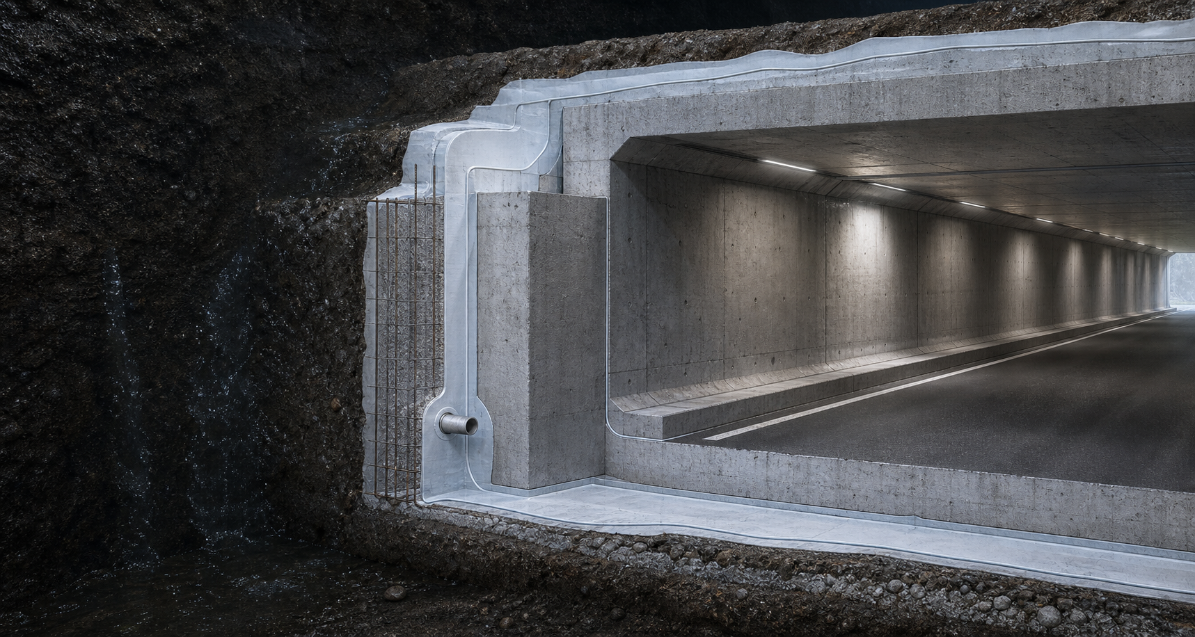
Positive system building
This functional section shows a route on the positive water side. The actual structure follows from water pressure, subsurface and project specification.
View tunnel and construction waterproofing →Critical detail areas
The transition between foundation slab and wall combines pour seam, geometry and possible water pressure.
Water stops, injection hoses, profiles and connection to surface sealing must be continuous during each pouring phase.
Pipes, jackets, anchors and installations are given a suitable flange, sleeve or injection detail.
The transition from ground to facade must drain rain, splash water and capillary transport in a controlled manner.
Internal and external corners plus movement joints require local reinforcement or a separate profile.
Insulation, drainage, protective plates and soil fill must not damage the waterproof layer.
Failure risks
An inner seal cannot automatically withstand negative pressure or water transport behind the layer.
Water accumulation and hydrostatic pressure can increase when drainage and soil building are not coordinated.
Debris, compaction, reinforcement or follow-up work can still pierce a controlled membrane after release.
One mistake at the bilge, pouring joint or penetration can break the entire underground shell.
Active or structural cracks cannot be treated as a static surface.
After backfilling, outdoor restoration is drastic; control and any injection points must be organized in advance.
From groundwater image to file
Record groundwater level, pressure, soil, drainage, leakage pattern and water side.
Assess concrete, pouring phases, joints, cracks, penetrations, existing layers and accessibility.
Design planes, bilges, joints, injection, drainage, protection and ground level detail as one shell.
Practically confirm preparation, bonding, detailed execution, work areas and covering order.
Check each zone after preparation, details and membrane separately before protection and replenishment.
Bundling drawings, photos, injection points, deviations and inspection data on a location-related basis.
Quality assurance
Demonstrably distinguish between ground moisture, non-pressure or pressure water and seasonal influence.
Strength, moisture, pores, gravel nests, cracks and repairs appropriately prepared.
Gums, work joints, penetrations and corners checked before closing the surface.
Wall, floor, foundation and ground level connect without unexplained interruption.
Consumption, coverage and local reinforcement registered per work area.
Protective plates, insulation and drainage installed without damage.
Material, equipment and compaction tailored to the protective layer and construction.
Photos, drawings, deliveries, deviations and repair points linked to building part.
Technical limits
Without water and soil data, the required system resistance cannot be reliably determined.
Settlement, stability and active cracks are first assessed by a qualified specialist.
Drainage is not a substitute for waterproofing, but it can determine the actual load.
A negative interior solution requires a separate study into water transport, adhesion and repairability.
Our project evidence
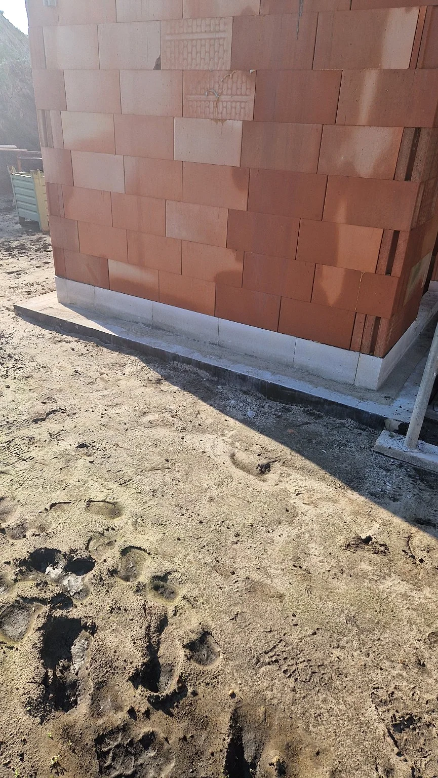
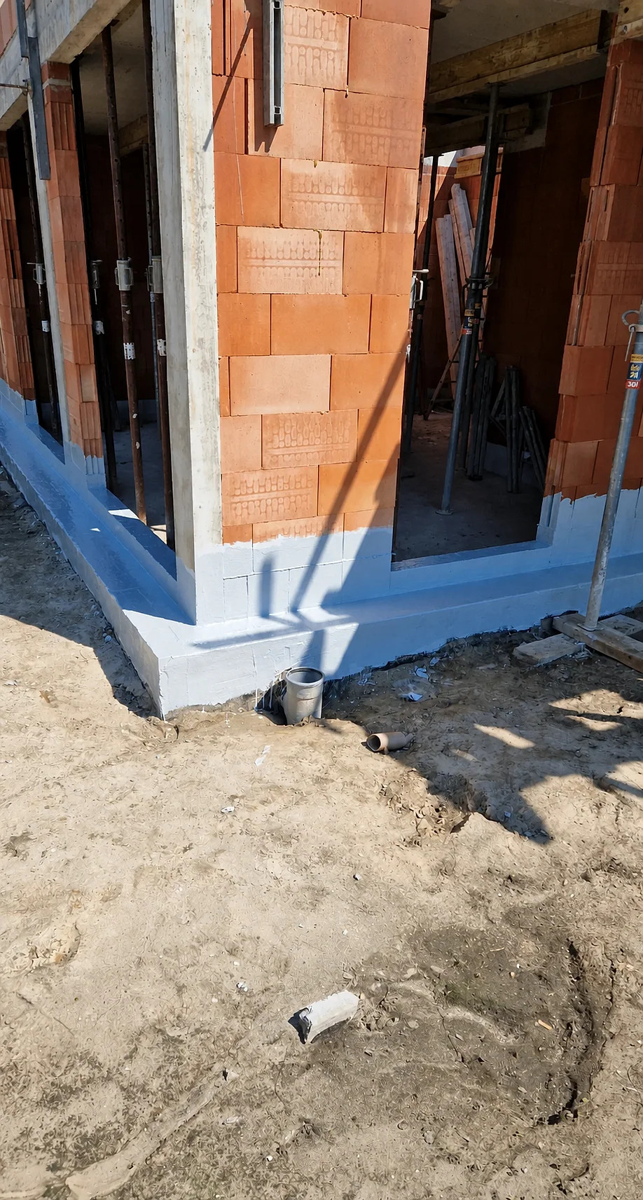
Approximately 200 m² of foundation waterproofing with primer, geotextile reinforcement and a continuous 2K membrane.
For technical pre-selection
Wall, floor, foundation, bilge, pouring phases, joints and penetrations.
Groundwater level, pressure, soil structure, drainage and seasonality.
Cracks, gravel nests, moisture, repairs and previous injections.
Positive or negative side, excavation, work space and safety.
Insulation, drainage, protective plate, supplementary material and ground level.
Pouring phases, covering moments, lifespan, drought class and contract documents.
Technical construction screening
Share drawings, groundwater data, concrete condition, details, accessibility and planning. We make visible which research and system choices are necessary for a technically responsible next step.